

 English
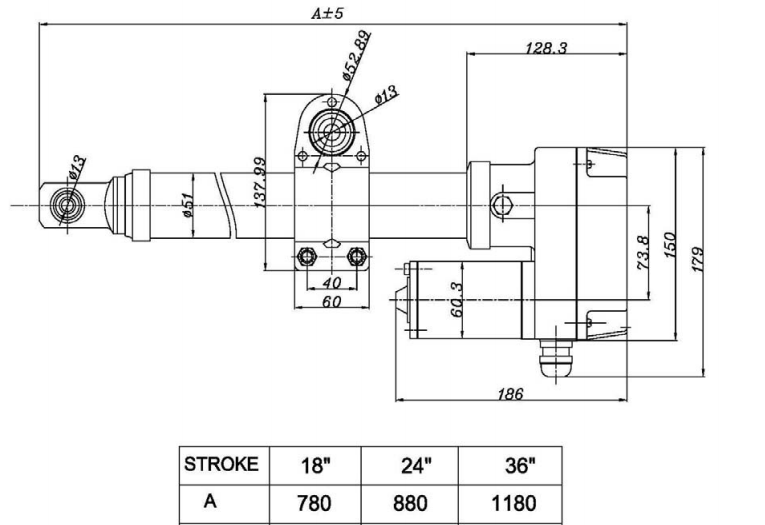
Dimensions:
User manual:3. Connect the DC positive (+) power wire to terminal 1 and the DC negative (-) power wire to terminal 2 on the terminal block as shown below. 4. Apply 12/24VDC to move the actuator; if the actuator moves in the direction opposite to that intended, reverse the red and black wires.
Reed Sensor (Optional)
1. Run two 22 gauge stranded shielded motor sensor wires through the locking grommet (green and brown shown).
2. Connect the sensors pulse and ground to terminals 3 and 4 as shown above.
3. Do NOT connect the 24-36V DC motor wires of the positioner to the reed sensor switch.
MOUNTING
1. Secure or remove the load before installation and ensure the mounting structure can support the possible load.
Put the actuator in the retracted position to position the load accurately with respect to the lifting screw centerline. Never pull
the translating tube to one side to make connection with your structure. Fully extend the actuator to make sure the load is
aligned with the translating tube.
3. Mount the actuator by securing the top mounting hole to a fixed position using 12mm diameter bolts. The stroke length of the
actuator (e.g. 18") and the limitations of the particular application will determine the location of the fixed mounting positions.
4. Locate the indluded electroplated mounting hardware (saddle clamp and two 12mm bolt assembly). The saddle clamp allows
the actuator to be mounted at any position along the length of the tube, which helps to accommodate a variety of mount types.
5. Slide the clamp down the shaft of the actuator to the desired mounting location on the shaft. The exact mounting location on
the shaft will depend on the mounting configuration of the end user. After the clamp is in the desired the location, securely
tighten the two nut/bolt pairs on the clamp. This will securely compress the clamp on to the shaft of the actuator
IMPORTANT: Confirm up/down movement of actuator is smooth and within actuators stroke length after installation.
LIMIT SWITCH - STROKE LENGTH ADJUSTMENT
CAUTION: Adjustment of limit switches on a linear actuator requires basic knowledge of geared electric motor functions. End users
lacking this knowledge are strongly advised to seek professional help when adjusting limit switches. Failure adjusting limit switches
properly can result in permanent damage to the linear actuator that is not covered under Windy Nation's warranty.
NOTE: The limit-switches are factory-set for stroke-length and protection of the motor unit against over-extending. Do not .
run the actuator until the limits switches are set properly (if the limit switches have been adjusted).
Check Upper Limit
1. If the actuator reaches the farthest extension point:
Remove the housing cover on the bottom of the linear actuator by removing the four screws.
b. Loosen the limit Lock screw as shown so the Limit Adjust can move freely, but do not remove.
C. Very slowly turn the Limit Adjust counter-clockwise (i.e. moving towards the upper limit switch) %4 turn.
d. Tighten the limit Lock screw and replace the housing cover.
2. If the actuator cannot reach the farthest extension point:
a. Remove the housing cover on the bottom of the linear actuator by removing the four screws.
b. Loosen the limit Lock screw as shown so the Limit Adjust can move freely, but do not remove.
C. Loosen the limit cam screw, but do not remove.
d. Very slowly turn the Limit Adjust clockwise (i.e. Moving away from the upper limit switch) in small increments to
extend the actuator slowly. Do not allow the actuator to extend all the way out.
Check to see if the actuator can now reach the farthest extension point. If it can, follow procedures in step 1 to
set the upper limit. If it does not you may need a longer actuator.
f. Tighten the limit Lock screw and replace the housing cover.


